

Electrical work becomes easier when a few basic ideas start to connect.
Voltage, current, resistance, and power are not just classroom terms. They explain why a motor will not start, why a connection overheats, why voltage drops when a load turns on, and why a breaker trips.
These electrical power basics matter whether you are brand new, working around generators, helping maintain a building, studying for an exam, or trying to get better at troubleshooting. You do not need to know everything at once. But you do need a solid way to think through what is happening in a circuit.
This guide explains the core ideas new technicians should understand before moving deeper into generators, transformers, motors, breakers, relays, testing, and troubleshooting.
What is electrical power?
Electrical power is the rate at which electrical energy is delivered or used.
That energy may turn a motor, run a pump, produce heat, light a building, charge a battery, power a control circuit, or feed an entire facility. In simple terms, electrical power is what allows electrical energy to do useful work.
Most electrical systems have three basic parts:
- The source supplies electrical energy.
- The conductors provide a path for current.
- The load uses the energy to do work.

A source may be a utility transformer, generator, battery, inverter, solar system, or power supply. A load may be a motor, heater, lighting circuit, battery charger, computer, pump, fan, or control panel.
Between the source and the load, you will usually find other equipment that controls, protects, or monitors the system. This may include breakers, fuses, switches, contactors, relays, meters, grounding conductors, bonding jumpers, transformers, and control wiring.
That is why troubleshooting is rarely about one part by itself. A failed load may be the final symptom, but the real issue could be with the source, wiring, protection, controls, environment, or mechanical equipment connected to the load.
Voltage, current, resistance, and power
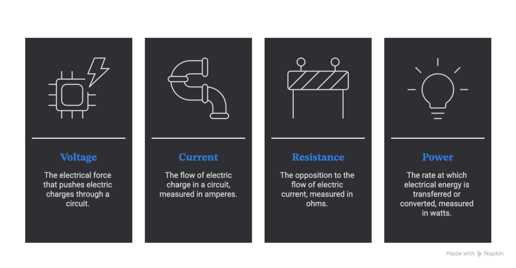
Most electrical learning starts with four terms: voltage, current, resistance, and power.
These are basic words, but they show up in almost every real electrical problem.
Voltage
Voltage is the electrical difference between two points. It creates the force that can move current through a complete circuit.
Voltage is measured in volts.
A common beginner explanation is that voltage is like pressure in a water system. That comparison is not perfect, but it helps explain the idea of electrical push.
In the field, voltage readings help answer important questions:
- Is power available?
- Is the voltage too high or too low?
- Is voltage present where it should not be?
- Is there voltage on all phases?
- Is there a voltage drop across a connection, conductor, fuse, or contact?
A circuit can have voltage present even when a load is not operating. That is one reason technicians should never assume equipment is safe just because it is not running.
Current
Current is the movement of electric charge through a circuit.
Current is measured in amperes, usually called amps.
A load draws current when it is connected to a suitable voltage source through a complete path. Motors, heaters, lights, chargers, and other loads all draw current when they operate.
Current tells you what the equipment is actually doing under load. A motor may have correct voltage at the terminals, but if it is drawing too much current, something else may be wrong. The motor may be overloaded, mechanically binding, losing a phase, running at low voltage, or operating under poor power conditions.
Current is also what causes heating in conductors and equipment. More current means more heat. That is why conductors, breakers, fuses, contactors, and terminals must be sized and maintained correctly.
Resistance
Resistance is opposition to current flow.
Resistance is measured in ohms.
Every conductor, connection, and load has some resistance. Good conductors have very low resistance. Loads are designed to have the right amount of opposition to current so they can do useful work.
Unwanted resistance is a common field problem. A loose, dirty, corroded, or damaged connection can add resistance to a circuit. That resistance can cause voltage drop, heat, arcing, nuisance trips, or equipment failure.
This is why a bad connection may not show up when equipment is off. The connection may look normal during a quick visual inspection. But under load, it can heat up and fail.
Power
Power tells you how quickly electrical energy is being delivered or used.
Power is measured in watts.
A motor converts electrical power into mechanical work. A heater converts electrical power into heat. A light converts part of that power into light and part of it into heat.
Power matters because it tells you how much work the electrical system is supporting. A generator may produce the correct voltage with no load connected, but that does not mean it can handle the load once motors, pumps, heaters, or other equipment start drawing power.
A simple way to remember the four terms is:
Voltage pushes. Current flows. Resistance opposes. Power does the work.
That may sound simple, but it is a useful way to think through many real problems.
Basic electrical formulas technicians should know
You do not need to be a math expert to work in electrical systems, but a few formulas help connect what you see on a meter to what is happening in the circuit.
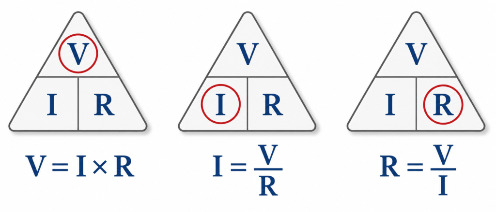
Ohm’s law
Ohm’s law describes the relationship between voltage, current, and resistance:
V = I × R
Where:
- V is voltage in volts
- I is current in amps
- R is resistance in ohms
For example, suppose 12 volts are applied across a 6-ohm load:
I = V ÷ R
I = 12 ÷ 6
I = 2 amps
This is a simple example, but the idea matters. If resistance changes, current changes. If voltage changes, current can change. When technicians understand that relationship, many problems become easier to explain.
Basic power formula
For a simple DC circuit or a resistive AC circuit:
P = V × I
Where:
- P is power in watts
- V is voltage in volts
- I is current in amps
A 120-volt load drawing 5 amps uses:
P = 120 × 5
P = 600 watts
AC power systems can become more complex because phase angle and power factor may also matter. Power factor describes how effectively current is being used to do real work in an AC circuit. Motors, transformers, and other inductive loads can make this more important.
Still, the basic idea remains useful: voltage and current together tell you how much electrical work is being done.
Why electrical power basics matter in the field
Advanced equipment still follows basic electrical rules.
A generator may produce the correct voltage but still struggle when the load is applied. A motor may draw high current because the voltage is low, the load is too heavy, or the driven equipment is binding. A loose terminal may add resistance, create heat, and damage the connection. A breaker may trip because it is protecting the circuit from current that is higher than normal.
The basics help you avoid guessing.
Without a strong foundation:
- Generator loading is harder to understand.
- Voltage drop is harder to diagnose.
- Motor current readings are easier to misread.
- Kilowatts and kilovolt-amperes are easier to confuse.
- Grounding and bonding become harder to follow.
- Protective devices look like problems instead of clues.
- Troubleshooting turns into part swapping.
Experienced technicians still use the basics every day. They may not explain them out loud, but they are thinking through source, load, voltage, current, resistance, protection, and safety every time they troubleshoot.
AC and DC power
Electrical systems commonly use alternating current or direct current.
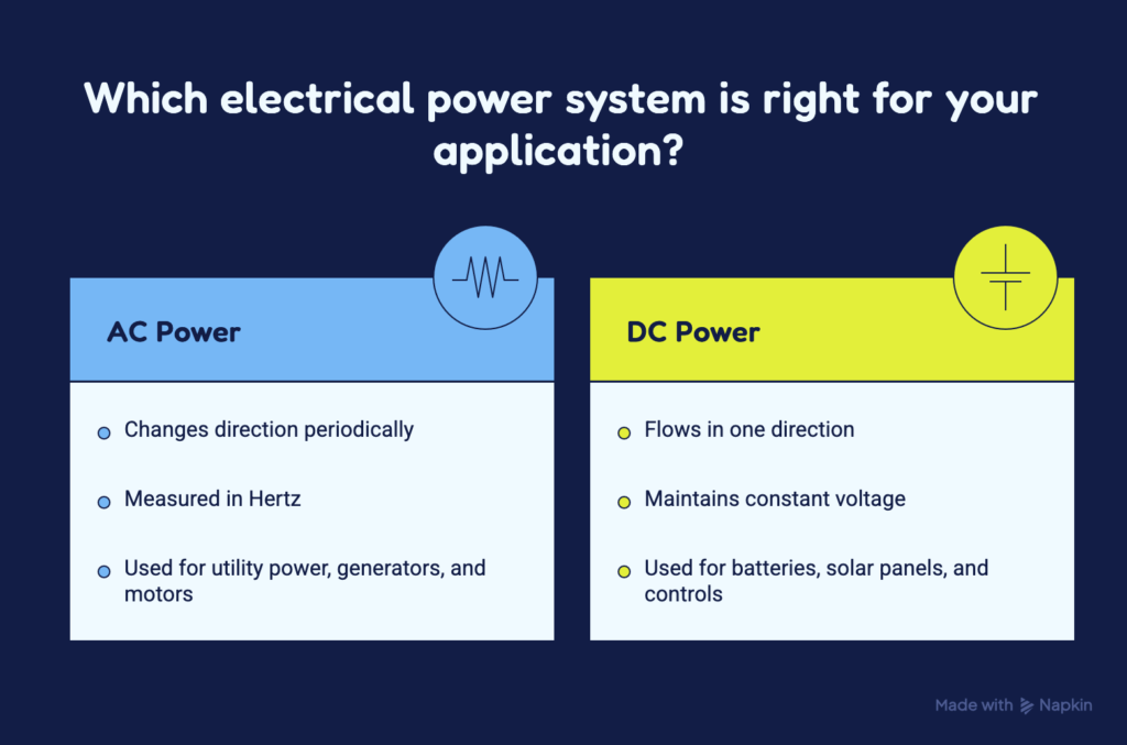
Alternating current
Alternating current, or AC, repeatedly changes direction.
Utility systems, building power, generators, transformers, and most large motors use AC. In the United States, most AC power systems operate at 60 hertz. Hertz is the unit used to measure frequency. A frequency of 60 hertz means the AC waveform completes 60 cycles each second.
AC power is common because it can be transformed to higher or lower voltages efficiently. This makes it useful for sending power over long distances and distributing it through buildings and facilities.
Direct current
Direct current, or DC, flows in one direction.
DC is common in batteries, solar panels, electronic circuits, generator starting systems, control circuits, protective relay systems, and battery energy storage systems.
Technicians must know whether a circuit is AC or DC before testing it. The meter setting, expected reading, polarity, and test method may be different.
Using the wrong meter setting or placing the test leads in the wrong ports can damage the meter, damage equipment, or expose the technician to a serious hazard.
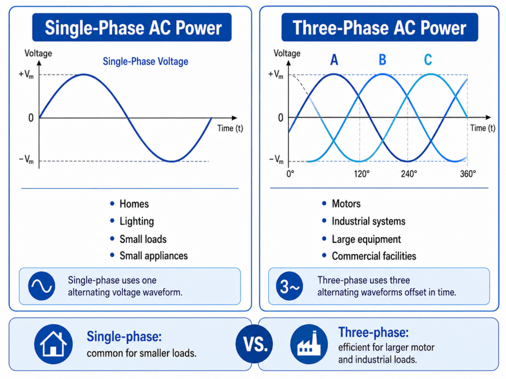
Single-phase and three-phase power
AC systems may be single-phase or three-phase.
Single-phase power
Single-phase power is common in homes, small buildings, lighting circuits, receptacles, small appliances, and smaller motors.
Many people first learn electrical work through single-phase systems because they are common in residential and light commercial settings. These systems are still important, but they are only part of the larger electrical world.
Three-phase power
Three-phase power uses three AC waveforms separated from each other by 120 electrical degrees.
Three-phase power is common in commercial buildings, industrial facilities, utility systems, generator plants, pump stations, data centers, and large motor systems.
Three-phase power can deliver power to large loads efficiently. It also creates a rotating magnetic field that works well with many AC motors.
When checking a three-phase system, technicians often look for:
- Correct phase-to-phase voltage
- Balanced voltage between phases
- Balanced current between phases
- Correct phase rotation
- Missing phases
- Loose or damaged connections
- Signs of overheating
- Correct operation of protective devices
A three-phase motor may overheat, rotate backward, lose torque, or fail to start if one phase is missing, the voltage is low, the system is badly unbalanced, or the phase rotation is wrong.
This is where the basics become practical. A motor problem is not always a motor problem. It may be a power supply problem, a connection problem, a control problem, or a mechanical problem.
Frequency and phase
Frequency tells you how many AC cycles occur each second. It is measured in hertz.
Frequency matters because many motors, generators, clocks, transformers, and control systems are designed for a specific frequency. In a generator system, low frequency may indicate that the engine is running too slowly or that the load is too heavy for the generator to support.
Phase describes the timing relationship between AC waveforms.
In a three-phase system, the phases are separated in time. That separation allows the system to deliver power smoothly and operate three-phase motors.
Technicians may need to check phase rotation before starting a three-phase motor. If phase rotation is wrong, the motor may turn in the wrong direction. On a pump, fan, or compressor, that can damage equipment or create unsafe operating conditions.
Sources and loads
One of the best troubleshooting habits is to identify the source and load before taking measurements.
The source is where the power comes from. The load is the equipment using the power.
That sounds obvious, but it helps prevent tunnel vision.
Suppose a pump will not run. The pump itself may be faulty, but the problem could also be in the utility source, generator, breaker, fuse, disconnect, motor starter, contactor, overload relay, control transformer, float switch, pressure switch, interlock, conductors, or terminals.
If you focus only on the pump, you may miss the real problem.
Before chasing the fault, ask:
- Where does the power come from?
- What equipment should receive it?
- What voltage should be present?
- What must happen before the load can operate?
- What changed before the problem started?
Good troubleshooting usually follows the system from source to load. It checks what should happen at each point, then compares that to what is actually happening.
Neutral, grounding, and bonding
Neutral, grounding, and bonding are related, but they do not mean the same thing.
Neutral conductor
A neutral is a current-carrying conductor in systems that use one.
Under normal operating conditions, the neutral may carry return current from certain loads. Not every electrical system or load uses a neutral.
New technicians sometimes think neutral and ground are the same because they may be connected at a specific point in the system. They are not the same. They have different jobs.
Equipment grounding conductor
An equipment grounding conductor connects non-current-carrying metal parts to the grounding and bonding system.
It should not normally carry load current.
During a fault, it helps provide a low-impedance path back to the source. This allows enough fault current to flow for a breaker, fuse, or other protective device to operate.
Low impedance means the path has very little opposition to AC current.
Bonding
Bonding connects conductive parts together.
Metal enclosures, raceways, equipment frames, grounding conductors, and bonding jumpers may be connected together so they remain at the same electrical potential and help provide an effective fault-current path.
A useful starting point is this:
The neutral may carry current during normal operation. Grounding and bonding are mainly there for safety and fault clearing.
Grounding and bonding can get complex quickly. Requirements depend on the system design, grounding method, equipment, code rules, drawings, and manufacturer instructions.
Do not guess your way through grounding and bonding work. Follow approved drawings, current code requirements, company procedures, and manufacturer instructions.
Breakers, fuses, and protective relays
Electrical systems need protection because failures happen.
Conductors can short. Motors can overload. Insulation can fail. Terminals can loosen. Equipment can break down. Someone can make a wiring mistake. Water, heat, dirt, vibration, and age can all create problems.
Common protective devices include:
- Circuit breakers
- Fuses
- Motor overload relays
- Ground-fault protection
- Protective relays
These devices respond to abnormal conditions.
An overload occurs when equipment carries more current than it is designed to handle for a period of time. A short circuit is an unintended low-impedance connection between conductors at different electrical potentials. A ground fault occurs when current follows an unintended path to grounded metal or ground.
A tripped breaker is not always the cause of the problem. Many times, the breaker opened because it detected a problem somewhere else in the system.
This is one of the most important lessons for new technicians: the device that trips is often only the messenger.
Before resetting a breaker, ask why it opened. Repeatedly resetting a tripped breaker without finding the cause can damage equipment and expose workers to additional risk.
A practical approach to electrical troubleshooting
Good troubleshooting is a controlled process. It is not random testing, guessing, or replacing parts until the equipment starts working again.
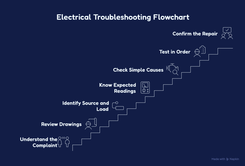
Start with these steps.
Understand the complaint
Find out what the equipment is doing and what it should be doing.
“Motor will not run” is useful, but it is not enough. Does the motor hum? Does the starter pull in? Does the breaker trip? Does it trip right away or after running? Did this happen after maintenance, rain, a load change, or a power outage?
The more specific the complaint, the better your troubleshooting path will be.
Review the system
Use drawings, one-line diagrams, schematics, equipment labels, manuals, and operating history when available.
A one-line diagram shows the main electrical path through a power system. A schematic shows how a control circuit operates. Both can save time and prevent wrong assumptions.
Identify the source and load
Know where power starts and where it should go.
If you do not know the source, you may miss another feed, backfeed, control circuit, or stored energy source.
Know the expected readings
Do not take measurements without knowing what you expect to see.
Before placing meter leads on a circuit, ask yourself what voltage, current, or resistance should be present and what each possible reading would mean.
Check simple likely causes first
Simple does not mean careless. It means logical.
Look for open disconnects, blown fuses, tripped overloads, loose connections, missing control power, active interlocks, failed switches, and obvious signs of heat or damage.
Test in order
Follow the circuit instead of jumping around.
Random measurements can create confusion. A logical path helps you narrow the problem step by step.
Confirm the repair
After the problem is corrected, verify that the equipment operates correctly. Check that the original issue is gone and that the system is safe to return to service.
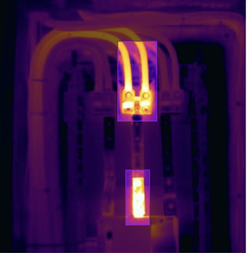
Field example: a motor keeps tripping
A technician is called to inspect a three-phase motor that repeatedly trips its breaker.
It may be tempting to assume the breaker is bad. That is possible, but it should not be the first conclusion.
The technician should first gather information:
- When does the breaker trip?
- Does it trip during startup or after running?
- Was the motor recently replaced or serviced?
- Has the driven equipment become hard to turn?
- Did the problem begin after rain, flooding, overheating, or maintenance?
- Has the load changed?
- Are there alarms, relay targets, or trip records?
The next checks may include:
- Confirming the correct supply voltage
- Checking all three phase-to-phase voltages
- Comparing current on each phase
- Looking for a missing phase
- Checking terminals for looseness or heat damage
- Inspecting the motor and driven equipment for mechanical binding
- Comparing overload and breaker settings with equipment ratings
- Reviewing the starter, control circuit, and protective device operation
The fault may be in the motor, conductors, starter, driven load, power source, connections, environment, or protection.
The point is not to make the problem complicated. The point is to avoid guessing. A good technician uses evidence to narrow the fault.
Common mistakes new technicians make
Treating voltage and current as the same thing
Voltage and current are related, but they are different.
A circuit can have voltage present without current flowing. Current requires a complete path and a connected load.
That is why a voltage reading by itself does not always prove the circuit can support the load.
Assuming “off” means safe
An open disconnect may still have energized line-side terminals. A panel may have more than one source. Control voltage may come from another circuit. Batteries, capacitors, springs, rotating equipment, and other components may store energy.
Always use the approved process for establishing an electrically safe work condition.
Taking measurements without a plan
Before using a meter, know what you are measuring, whether the circuit is AC or DC, what reading you expect, where the leads belong, what meter rating is required, and what hazards are present.
A meter should confirm or reject a specific idea. It should not be used to poke around until something looks interesting.
Ignoring connections
Loose, corroded, dirty, or damaged connections can create resistance.
A bad connection may look normal when equipment is off. Under load, it can produce voltage drop and heat. Over time, that heat can damage terminals, insulation, contact surfaces, or nearby equipment.
Replacing parts before finding the cause
Replacing a breaker, fuse, relay, or contactor without testing may hide the problem for a short time. It can also waste money and create new problems.
Use measurements, inspection, drawings, and operating history to support the diagnosis.
Quick electrical troubleshooting checklist
Before testing equipment, ask:
- What is the power source?
- What is the load?
- Is the system AC or DC?
- Is it single-phase or three-phase?
- What voltage should be present?
- What current should the load normally draw?
- What conditions must be met before the equipment can operate?
- What protective device opened?
- Are alarms, relay targets, or trip records available?
- Are drawings and manuals available?
- What changed before the fault appeared?
- Has the correct safety procedure been completed?
This checklist is simple, but it keeps your thinking organized. That matters when equipment is down, people are waiting, and there is pressure to hurry.
Electrical safety comes first

Electrical equipment can expose workers to shock, arc flash, burns, fire, and stored-energy hazards.
Do not depend only on a label, switch position, indicator light, or another person’s statement that a circuit is off.
Follow the approved lockout/tagout procedure. Identify every energy source. Use properly rated test equipment. Verify your tester before and after checking for absence of voltage. Wear the required personal protective equipment and follow the applicable electrical safety program.
The best technician is not the person who opens the cabinet first. It is the person who understands the system, controls the hazards, and follows a logical process.
Conclusion
Electrical power basics give technicians a practical way to understand equipment and solve problems.
Start with voltage, current, resistance, and power. Then learn how AC, DC, frequency, phase, sources, loads, grounding, bonding, and protective devices fit together.
These ideas show up again when working with motors, generators, transformers, switchgear, relays, and electrical tests.
When a system fails, return to the basics:
Where is the power coming from? Where should it go? What should the readings be? What changed?
Those questions are often the start of a good diagnosis.